English
 Русский язык
 بالعربية


Products Description
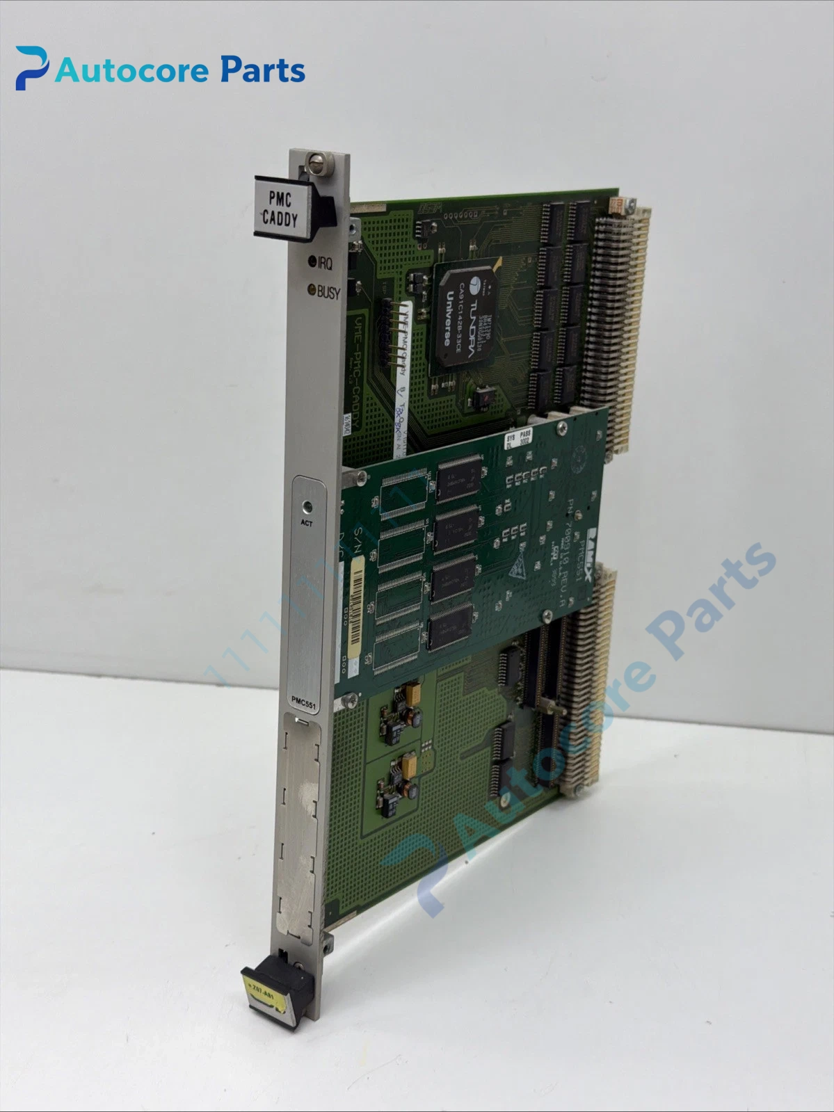
VME-PMC-CADDY PMC Carrier Board Unit

Module Feature
VME-PMC-CADDY is a 6U Eurocard VMEbus carrier board designed to host PMC (PCI Mezzanine Card) daughter modules.
It uses Universe II CA91C142D VME‑PCI bridge chip to realize protocol conversion between VME backplane bus and PCI local bus for PMC sites. It accepts two single-width PMC cards or one double-width PMC card, follows IEEE P1386 PMC mechanical and electrical specification. Onboard DIP coding switches set VME base address, interrupt mapping and bus mode. It gets 5V power supply from VME backplane and generates 3.3V power rail for PMC modules. It is commonly used to add Ethernet, serial, analog acquisition or communication PMC daughter boards to old VME control racks, and is a popular legacy spare for GE VMIC / Speedtronic rotating machinery control system maintenance.
Working principle
The VME bus master sends read/write commands to the carrier board.
Universe II bridge translates VME bus cycles into PCI bus transactions, routing data to the installed PMC mezzanine card. Interrupt signals from PMC modules are forwarded back to VME system via bridge logic. The carrier does not run application logic itself; it only acts as a transparent bus adapter to expand I/O and communication functions via PMC modules.
Onboard components
Universe II VME‑PCI bridge chip, PCI bus buffer circuit, DIP configuration switch bank, power regulation circuit for 3.3V, PMC site connectors, status LED array, 6U front panel, VME P1/P2 backplane edge connector and shielding structure.
LED indicators
Front LEDs indicate power supply, PCI bus activity, VME bus access and fault status.
Hardware self‑diagnosis
No dedicated onboard application self-test. Bus access error, PCI timeout and interrupt anomaly can be captured by VME chassis diagnostic tool and system firmware.
Programming softwareVME bus configuration utility, BIOS / VxWorks BSP driver, system diagnostic tool.
Electrical & Process Parameters
Model:VME-PMC-CADDY Brand:ESD / GE VMIC compatible carrier Device type:6U VMEbus PMC carrier adapter Function:VME to PCI bus conversion and mechanical carrier for PMC mezzanine expansion modules
Mechanical & Structure
Mounting:6U VME chassis slot plug-in installation Protection class:IP20 Housing:6U Eurocard industrial PCB with metal front panel
Environmental
Operating temperature:-20℃ ~ +70℃ Storage temperature:-40℃ ~ +85℃ Ambient humidity:5~95% non‑condensing
Certification:CE Status:Original legacy VME expansion spare
Installation
Power off chassis before replacement.
Install PMC daughter card onto carrier first, set DIP address switches, insert carrier into VME slot, verify bus mapping and driver loading before functional test.
Interface
VME64 P1/P2 backplane connector, two PMC mezzanine sockets, front panel status indicator interface.
Diagnostic
Bus access failure: Wrong DIP address setting, bridge chip damage or VME slot conflict. PMC not detected: PMC card incompatible, 3.3V power fault or poor connector contact. Interrupt abnormal: Interrupt routing conflict or firmware driver mismatch.
Product Brief
VME-PMC-CADDY carrier board, 6U VME to PCI PMC adapter spare for legacy GE VMIC and VME test control rack replacement.