English
 Русский язык
 بالعربية


Products Description
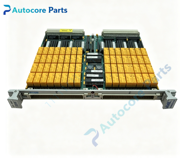
VMIC VMIVME-2210 Relay Output Board

Module Feature
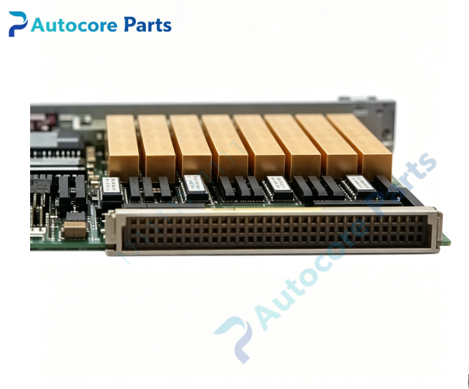
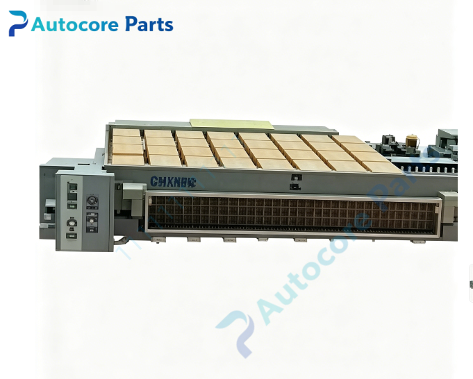
VMIC VMIVME-2210 is a single-slot 6U VMEbus relay output board with 64 magnetic latching SPDT form C relay channels. Magnetic latching relays maintain contact status even after power removal, suitable for offline fault isolation and safety interlock applications. Each relay provides common, normally open and normally closed contact terminals, rated up to 2 A, 250 VAC / 220 VDC per channel. Dual 96-pin DIN front panel connectors route all 64 relay contacts. DIP switch bank configures VME base address and selects latching / non-latching operating mode. Supports A16/A24 VME addressing and 8/16/32 bit data transfer modes. The board implements relay state readback function, allowing host software to verify actual contact position. Built-in BIT diagnostic circuit can check relay drive and contact integrity without disconnecting field wiring. Power-up lock function prevents unexpected relay switching during chassis power on/off transient. Rugged Eurocard construction, widely used in power plant safety interlock, gas turbine auxiliary control, aerospace hardware test bench and factory emergency shutdown VME systems.
Working principle
VME host writes command register to trigger relay set or reset pulse for magnetic latching coils. Once the latching relay changes state, it holds position without continuous coil energization. The readback register samples real relay contact status and returns data to VME CPU for state verification. DIP switches set VME base address and operating mode. BIT circuit generates test signals to validate drive circuits and contact paths. VME slave interface completes address decoding and data handshake for register read and write operations. Contact surge suppression network absorbs inductive load back EMF to protect relay contacts and onboard electronics.
Onboard components
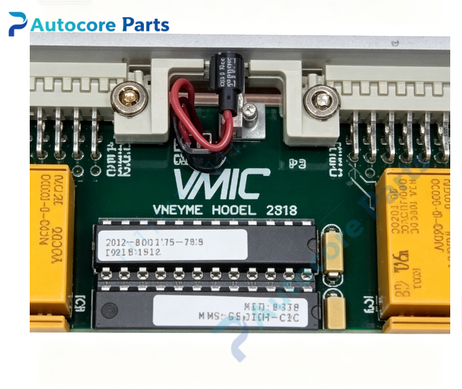
64 magnetic latching SPDT relay array, relay coil pulse drive circuit, contact readback sensing network, BIT built-in test logic, VME address decode gate array, DIP address switch bank, dual 96-pin DIN front panel connectors, contact surge suppression components, status LED array.
LED indicators
Front panel LED indicators for board +5 V power, BIT fault alarm and VME bus activity. Individual relay contact state is obtained via software register readback.
Hardware self-diagnosis
Visual inspection of PCB, front ejectors and solder joints; board ID register readback verification; BIT relay write-readback loop test for all 64 channels; DIP switch address and operating mode validation; contact surge protection circuit check; VME 8/16/32 bit read/write communication test.
Programming software
VMIC VME device driver library, universal relay I/O configuration and BIT diagnostic utility, compatible with VxWorks, Linux and Windows embedded real-time operating systems.
Electrical & Process Parameters
Model: VMIVME-2210 Brand: VMIC Device type: 6U VMEbus magnetic latching relay output module Bus standard: VMEbus, A16/A24 addressing, 8/16/32 bit transfer Channel count: 64 SPDT form C magnetic latching relay channels Contact rating: Max 2 A, 250 VAC / 220 VDC per channel Control mode: VME slave access, latching/non-latching mode selectable, relay state readback, BIT built-in self-test Power supply: +5 V from VME backplane Cooling: Convection cooling Protection: Contact surge suppression, power-up relay lock, ESD protection Mounting: Standard 6U VME front panel ejector locking Protection class: PCB with optional conformal coating
Mechanical & Structure
Mounting: Standard single-slot 6U VME Eurocard Protection class: PCB with optional conformal coating
Environmental
Operating temperature: 0℃ ~ +60℃ Storage temperature: -40℃ ~ +85℃ Ambient humidity: 5~95% non-condensing Certification: CE compliant Status: VMIC 64 channel magnetic latching VME relay output board
Installation
Follow ESD safety procedure before handling. Fully power off VME chassis. Insert VMIVME-2210 into vacant 6U VME slot and lock front panel ejector latches. Set DIP switches for VME base address and relay operating mode. Wire field loads and interlock circuits to dual 96-pin DIN front connectors. Power on chassis, load VMIC VME driver, execute BIT channel test before commissioning.
Interface
VME J1/J2 backplane connector, dual front-panel 96-pin DIN connectors for relay contact signals, fault status signal pins.
Diagnostic
Board undetected: poor VME backplane contact, damaged edge connector, incorrect DIP address switch setting. Relay cannot toggle: coil drive circuit fault or relay coil burnout. Readback state mismatch: contact wear or readback sensing circuit failure. Unexpected relay switching: power transient without enable of power-up lock function.

Product Brief
VMIC VMIVME-2210 single height 6U VME relay output board,64 magnetic latching SPDT relay channels retaining state during power loss,with BIT self-test and relay state readback,for power plant safety interlock,turbine auxiliary control and aerospace test bench VME control systems.