English
 Русский язык
 بالعربية


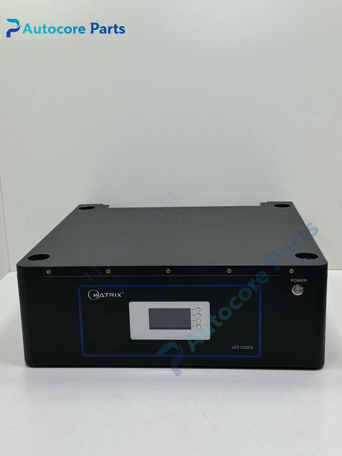
Products Description
JZ5120ES Boost Switching Controller IC Unit

Module Feature
JZ5120ES is a current-mode boost PWM controller chip. It adopts built-in loop compensation structure to reduce peripheral component count. It supports wide voltage input range, suitable for lithium battery stack, 24V industrial bus and low voltage power conversion occasions. It features cycle-by-cycle peak current limiting, under-voltage lockout and thermal shutdown protection. Compact SMD package for PCB layout inside control board, drive board and sensor transmitter circuit. Widely stocked as spare for industrial automation power repair.
Working principle
The internal oscillator generates fixed frequency PWM signal. The error amplifier compares feedback voltage with internal reference, adjusts PWM duty cycle to stabilize output voltage. Inductor stores energy during switch on period and releases energy to output capacitor during off period to realize boost conversion. Current sampling circuit monitors inductor peak current for overcurrent protection.
Onboard components
PWM logic circuit, error amplifier, current sense comparator, internal reference, oscillator, thermal protection circuit and power MOS gate driver.
LED indicators
No built-in LED indicator.
Hardware self‑diagnosis
Internal thermal and UVLO monitoring. Protection threshold is fixed inside chip, no local adjustment.
Programming software
Not applicable, hardware fixed function, no configuration software required.
Electrical & Process Parameters
Model: JZ5120ES Brand: Generic power IC Device type: Boost DC-DC controller IC Function: Step-up voltage conversion and overcurrent / overheat protection for low power industrial power supply
Mechanical & Structure
Mounting: SMD soldering on PCB Protection class: Molded plastic package Housing: Plastic IC package
Environmental
Operating temperature: -40℃ ~ +125℃ Storage temperature: -55℃ ~ +150℃ Ambient humidity: 5~95% non‑condensing
Certification: RoHS Status: Original electronic component spare
Installation
Solder IC on PCB pad according to datasheet footprint, connect inductor, diode, input/output capacitor and feedback resistor network, verify output voltage and load stability after commissioning.
Interface
VIN power pin, FB feedback pin, SW switch node pin, GND pin, EN enable pin.
Diagnostic
No output: UVLO triggered, wrong feedback resistor ratio or soldering open. Output unstable: Inductor saturation, insufficient output capacitance. Continuous restart: Overcurrent or short circuit on output side.
Product Brief
JZ5120ES IC, wide input current mode boost PWM controller spare for industrial board auxiliary power conversion circuit replacement.