English
 Русский язык
 بالعربية


Products Description
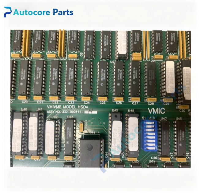
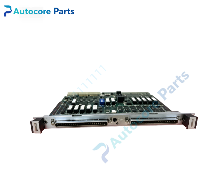
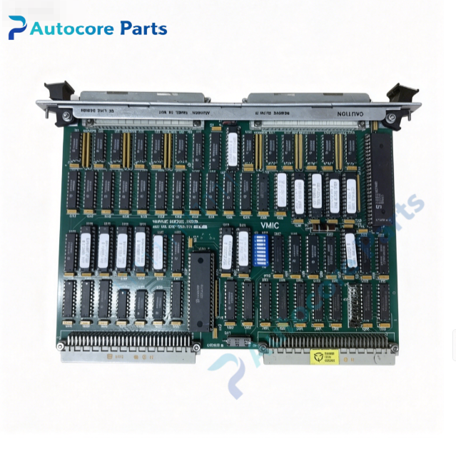
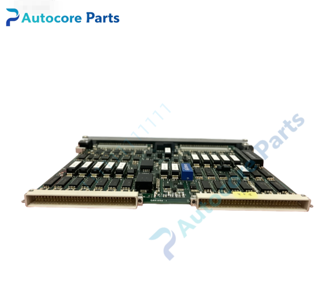
VMIC VMIVME-1111 Digital I/O Board

Module Feature
332-000111 (VMIVME-1111) is a single-slot 6U VMEbus high-density digital I/O board developed by VMIC (GE Fanuc / Abaco Systems). It provides total 96 bi-directional TTL-compatible digital I/O lines,divided into 12 independent 8-bit register groups. Each 8-bit port can be individually configured as input or output via software register. The board supports edge detection function for input channels,capable of capturing rising edge,falling edge or both edge events and triggering VME interrupt. Interrupt level and interrupt vector can be programmed flexibly to match VME system interrupt architecture. All I/O signals are routed through VME P2 rear connector for rear transition board wiring. Front panel fitted with status LED for interrupt activity and fault indication. Built-in BIT self-test writes and reads back digital patterns to verify register and I/O circuit integrity. Rugged Eurocard PCB with conformal coating,shock and vibration screened for power plant cabinet environment,widely used in gas/steam turbine multi-channel discrete signal control,aerospace ground test bench and hardware-in-loop real-time simulation VME chassis.
Working principle
VME host writes direction configuration register to set each port as input or output. For output ports,CPU writes logic states to output registers to drive TTL output lines. For input ports,hardware latches input logic level and edge events;when edge matches configured condition,an interrupt request is asserted to VME bus. BIT test writes predefined logic patterns to output registers and reads back through internal loopback path to validate every channel operation. VME FPGA handles address decoding,register access and VME interrupt generation.
Onboard components
VME interface FPGA,twelve 8-bit bi-directional I/O register banks,edge detection logic,interrupt control circuit,BIT pattern test hardware,VME J1/J2 edge connector,P2 rear I/O signal pins,front-panel status LED array.
LED indicators
Front panel LED indicators for interrupt activity and module fault alarm.
Hardware self-diagnosis
Visual inspection of PCB,components and solder joints;board ID register readback verification;BIT pattern write-read loopback test for all 96 channels;VME A16 register read/write communication validation.
Programming software
VMIC digital I/O driver library and configuration utility,supports VxWorks,Linux and QNX real-time operating systems;software tool for port direction setup,edge trigger selection,interrupt vector configuration and BIT fault log reading.
Electrical & Process Parameters
Model:332-000111 (VMIVME-1111) Brand: VMIC Device type: 6U VMEbus 96 channel bi-directional TTL digital I/O module Bus standard: VMEbus, A16 short addressing, D08/D16/D32 data transfer Channel:96 bi-directional TTL I/O,12 × 8-bit software configurable ports Signal level: TTL logic level Interrupt: Edge detection,programmable VME interrupt level & vector Control mode: VME slave access,per-port direction configuration,edge capture,BIT loopback self-test,TTL ESD clamping Power supply: +5 V from VME backplane Cooling: Convection cooling Protection: TTL signal ESD clamping Mounting: Standard single-height 6U VME front panel ejector locking Protection class: PCB with optional conformal coating
Mechanical & Structure
Mounting: Single-slot 6U VME Eurocard Protection class: PCB with optional conformal coating
Environmental
Operating temperature:0℃ ~ +70℃ Storage temperature:-40℃ ~ +85℃ Ambient humidity:20~80% non-condensing Certification: CE compliant Status: VMIC 6U VME high-density 96-channel TTL bi-directional digital I/O board
Installation
Follow ESD safety procedure before handling.Fully power off VME chassis.Insert 332-000111 (VMIVME-1111) into vacant 6U VME slot and lock front panel ejector latches.Set onboard jumpers for base address and interrupt modifier.Mate rear transition board to P2 connector for field wiring.Power on chassis,load VMIC digital I/O driver,run BIT loopback diagnostic before commissioning.
Interface
VME J1/J2 backplane connector,P2 rear I/O signal pins,interrupt and fault status register pins.
Diagnostic
Board undetected: poor VME backplane contact,damaged edge connector or incorrect base address jumper setting. BIT channel test failure: I/O transceiver hardware damage or register read/write fault. Edge interrupt missing: edge mode misconfiguration or noisy input signal. Port direction invalid: software register write error or FPGA configuration fault.

Product Brief
VMIC 332-000111 (VMIVME-1111) single height 6U VME digital I/O board,96 software-configurable bi-directional TTL channels with edge detection and programmable VME interrupt,built-in BIT loopback test,provides high-density discrete signal interface for turbine digital signal control and aerospace hardware-in-loop simulation VME systems