English
 Русский язык
 بالعربية


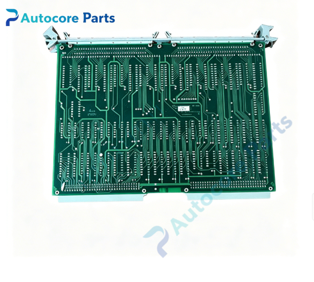
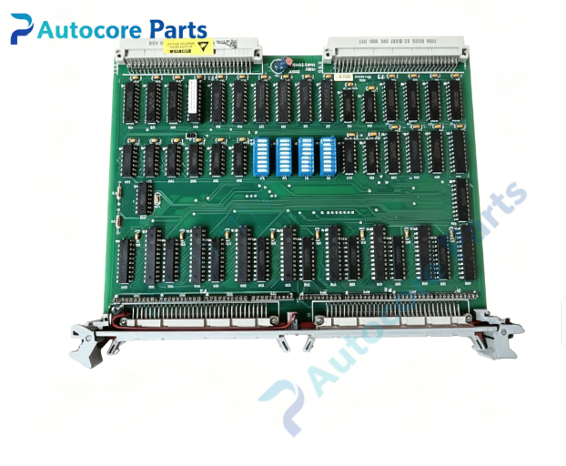
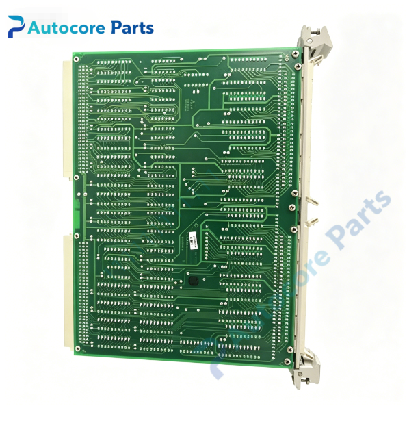
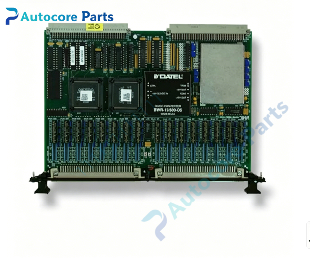
Products Description
VMIC VMIVME-2510B TTL Digital I/O Board

Module FeatureVMIC VMIVME-2510B is a single-slot 6U VMEbus digital I/O board belonging to VMIC Megamodule product family, providing total 64 TTL compatible I/O bits organized as eight independent 8-bit ports. Each 8-bit port can be individually programmed as input or output via control register. Output channel supports 64 mA sink current and 15 mA source current, optional open-collector output version available for external pull-up application. The board implements separate address decoding for control CSR register and data register; two sets of DIP address switches allow contiguous memory mapping for multi-board system to save VME address space. Supports 8-bit,16-bit and 32-bit VME data transfer modes. Onboard Built-In-Test (BIT) hardware supports online and offline fault detection & isolation, front panel dedicated Fail LED to indicate hardware fault status. Equipped with high-reliability DIN type I/O connector for field wiring connection. Rugged Eurocard construction, widely used in turbine control, aerospace test bench, industrial discrete signal monitoring and embedded simulation VME chassis.
Working principleVME host CPU writes port direction configuration to CSR register to define each 8-bit port as input or output. For input ports, external TTL logic signals are latched into data registers for VME master reading. For output ports, host writes digital logic levels to output registers to drive TTL output circuits. BIT logic can perform internal loopback test without disconnecting field cables, verifying integrity of each I/O path and report fault via CSR and front panel Fail LED. VMEbus slave interface handles address decoding, data handshake and interrupt generation on input state change.
Onboard components8 × 8-bit I/O port register array, TTL driver/receiver chips, BIT fault detection logic, VME address decode logic, control CSR register, DIP address switch bank, front panel DIN I/O connector, Fail status LED, optional open-collector transistor array.
LED indicatorsFront panel LED indicators: Fail fault indicator; board power and bus activity can be monitored via register read.
Hardware self-diagnosisVisual inspection of PCB, front ejectors and solder joints; board ID register readback verification; BIT offline and online loopback test for all 64 I/O bits; port direction switching test; VME 8/16/32 bit read/write communication test.
Programming softwareVMIC VME device driver library, universal Megamodule I/O configuration and BIT diagnostic utility, compatible with VxWorks, Linux and Windows embedded real-time operating systems.
Electrical & Process ParametersModel: VMIVME-2510B Device type: 6U VMEbus TTL digital I/O Megamodule Bus standard: VMEbus Total I/O bits: 64 bits, 8 × 8-bit programmable ports Logic level: TTL 5 V compatible Output rating: 64 mA sink,15 mA source per channel, optional open collector Control mode: VME slave access, port direction programming, BIT built-in self-test Power supply: +5 V from VME backplane Cooling: Convection cooling Protection: Over current, ESD protection Mounting: Standard 6U VME front panel ejector locking Protection class: PCB with optional conformal coating
Mechanical & StructureMounting: Standard single-slot 6U VME Eurocard Protection class: PCB with optional conformal coating
EnvironmentalOperating temperature: 0℃ ~ +60℃ Storage temperature: -40℃ ~ +85℃ Ambient humidity: 5~95% non-condensing Certification: CE compliant Status: VMIC 64 bit TTL VME programmable digital I/O board
InstallationFollow ESD safety procedure before handling. Fully power off VME chassis. Insert VMIVME-2510B into vacant 6U VME slot and lock front panel ejector latches. Set DIP address switches for CSR and I/O base address according to system address map. Wire field TTL sensors and actuators to front DIN I/O connector. Power on chassis, load VMIC VME driver, configure port direction and run BIT self-test before commissioning.
InterfaceVME J1/J2 backplane connector, front panel DIN multi-channel digital I/O terminal, fault status signal pins.
DiagnosticBoard not detected: poor VME backplane contact, damaged edge connector, incorrect DIP address switch setting. I/O port read/write failure: port direction register misconfiguration, field wiring short circuit, TTL driver chip damage. BIT test failure: I/O register fault or BIT logic hardware damage. Fail LED lit: board internal hardware fault detected by BIT circuit.

Product BriefVMIVME-2510B VMIC 6U VME 64 bit TTL digital I/O Megamodule,eight individually configurable 8-bit ports,with BIT fault detection and DIN field connector,for industrial discrete signal control and aerospace test VME systems.