English
 Русский язык
 بالعربية


Products Description
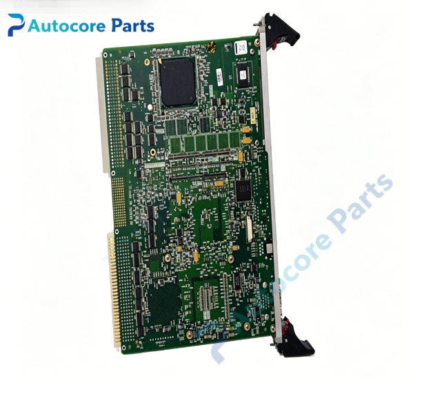
VMIC VMIVME-4514 Analog I/O Board
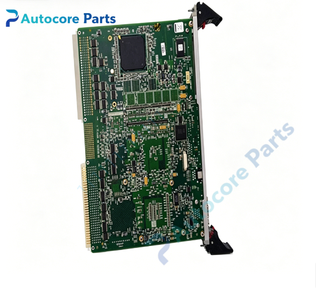
Module FeatureVMIC VMIVME-4514 is a double-slot 6U VMEbus analog input/output scanning module, equipped with 16 analog input channels and 16 analog output channels, both at 12-bit resolution. Analog input supports single-ended or differential signal wiring; optional 36 Hz low-pass anti-aliasing filter can be fitted for noise reduction. Each channel voltage range is configurable via onboard jumpers: unipolar 0~+5 V,0~+10 V; bipolar ±2.5 V,±5 V,±10 V. Every analog output channel supports max 10 mA drive current, 0.1 Ω low output impedance and short-circuit protection. Three ADC operation modes: auto scanning (power-on default), scanning poll and random polling, max ADC throughput up to 40 kHz. Built-in BIT(Built-In Test) function verifies all active components without external wiring, supports offline output disconnection for safe calibration. Analog signals are routed through rear P2 VME connector. Rugged double Eurocard construction, widely used in turbine closed-loop control, real-time simulation, semiconductor process control and test measurement systems.
Working principleIn auto-scan mode, onboard scanner continuously samples 16 analog input signals, conditions and converts them to digital data via 12-bit ADC, then stores sampling values into dual-port memory for VME host access. VME master writes digital setpoint data to DAC registers; each DAC converts digital codes to analog voltage through sample & hold amplifier. Onboard FPGA manages channel sequencing, VME address decoding and BIT diagnostic logic. Jumpers define full-scale voltage range for each channel; transient protection circuit suppresses overvoltage damage to ADC/DAC chips.
Onboard components12-bit ADC & DAC chip array, sample & hold amplifiers, signal conditioning and anti-alias filter circuit, overvoltage/short protection network, scan control FPGA, dual-port data memory, VME J1/J2 transceivers, BIT diagnostic logic, configuration jumpers, status LED indicators, P2 rear analog signal connector.
LED indicatorsFront panel LED indicators for board power, VME bus activity, analog signal fault and BIT failure alarm.
Hardware self-diagnosisVisual inspection of PCB, front ejectors and solder joints; board ID register readback and firmware verification; BIT full component self-test; per-channel ADC/DAC loopback calibration; full-scale and zero-offset accuracy validation; VME read/write communication test.
Programming softwareVMIC VME device driver library, analog channel configuration and calibration utility, compatible with VxWorks, Linux and Windows embedded real-time operating systems.
Electrical & Process ParametersModel: VMIVME-4514 Device type: Double-slot 6U VMEbus scanning analog I/O module Bus standard: VMEbus Rev C.1, A16/A24 VME slave addressing Resolution: 12 bit for AI and AO AI channels:16, single-ended / differential selectable AO channels:16, max 10 mA per channel Voltage range: Jumper configurable 0~5 V,0~10 V,±2.5 V,±5 V,±10 V ADC throughput: Max 40 kHz Control mode: Auto scan / scan poll / random poll, BIT built-in self-test Power supply: +5 V from VME backplane Cooling: Convection cooling Protection: Overvoltage, short-circuit and transient surge protection Mounting: Double-height 6U VME front panel ejector locking Protection class: PCB with optional conformal coating
Mechanical & StructureMounting: Double-slot 6U VME Eurocard Protection class: PCB with optional conformal coating
EnvironmentalOperating temperature: 0℃ ~ +55℃ Storage temperature: -40℃ ~ +85℃ Ambient humidity: 5~95% non-condensing Certification: CE compliant Status: VMIC double-slot VME high precision scanning analog I/O board
InstallationFollow ESD safety procedure before handling. Fully power off VME chassis. Insert VMIVME-4514 into vacant double-height 6U VME slot and lock front panel ejector latches. Set onboard jumpers for required voltage range of each channel. Wire analog sensors and actuators to rear P2 I/O connector. Power on chassis, load VMIC driver, run BIT self-test and channel calibration before commissioning.
InterfaceVME J1/J2 backplane connector, P2 rear multi-channel analog I/O terminal, fault status signal pins.
DiagnosticBoard undetected: poor VME backplane contact, damaged edge connector, abnormal backplane power. Analog channel offset drift: calibration aging, ground loop interference, signal conditioning circuit drift. AO no output: short-circuit protection triggered, broken field wiring, DAC hardware fault. BIT test failure: damaged ADC/DAC or FPGA logic error.
Product BriefVMIVME-4514 VMIC double height 6U VME scanning analog I/O board,16 channel 12 bit analog input and 16 channel analog output,with BIT self-test and auto scan mode,for turbine control,real-time simulation and semiconductor process measurement systems.